Clack-BASIC Compiler & 16-Bit Relay Architecture
High-precision three-address code (3AC) intermediate compilation, bitwise arithmetic, and hardware-tailored clock cycles for Peter's spectacular 16-Bit Relay Computer.
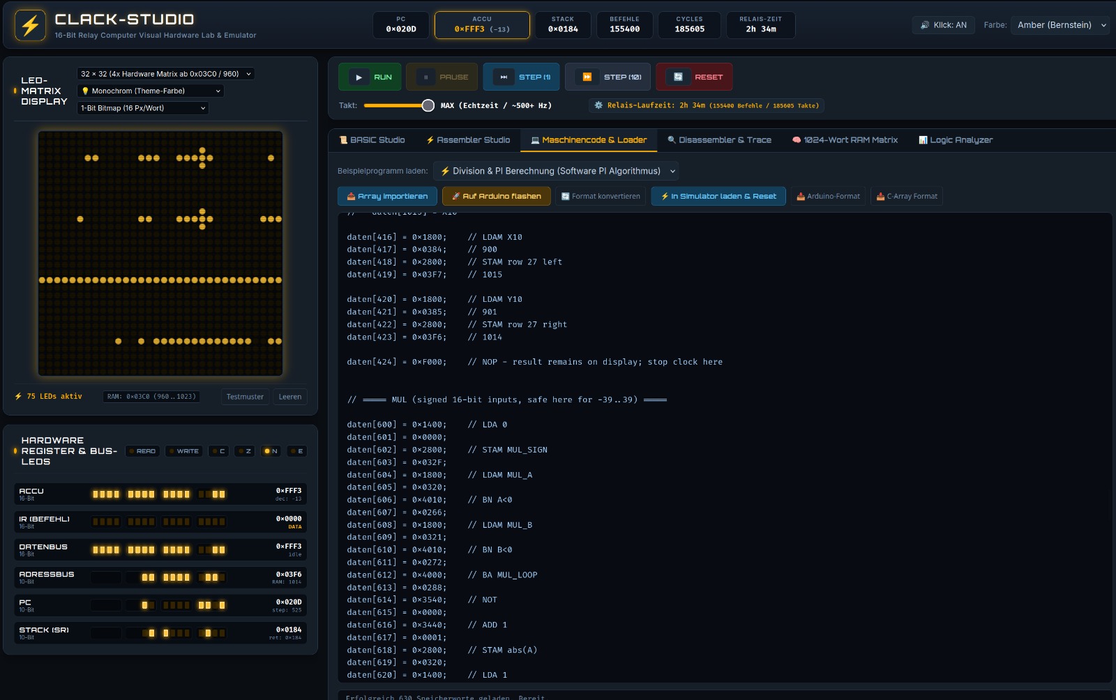
The computer designed and built by Peter operates with mechanical weak-current relays for sequencer control, registers, and timing, combined with diode matrices for the ALU. The system memory (1024 × 16-bit words = 2048 bytes) and clock generation are connected via Arduinos. The physical step duration is approx. 70 ms per microprogram step (each step consisting of four clock phases Clk0 through Clk3), resulting in physical instruction runtimes between ~140 ms (NOP) and ~560 ms (indirect memory operations).
⚙️ Register Architecture & Accumulator
The CPU is designed as a classic 16-bit accumulator architecture. Programmers interact primarily with the accumulator; internal registers handle sequencer execution:
ACCU(Accumulator): Central 16-bit computational and data register for all ALU operations and transfers.SR(Subroutine Return Register): 10-bit register holding the return address duringCALL / RET. Physically only one subroutine level exists (no hardware stack!). Nested calls require a compiler software stack in RAM.PC(Program Counter): 10-bit register (0 to 1023) pointing to the next instruction or operand word during execution.AR,AB-R,PC-HR: Internal 10-bit address, latch, and auxiliary sequencer registers.FLAGS: No unified status register! FlagsN(Negative / Bit 15),Z(Zero), andE(Even / Bit 0 == 0) are derived combinatorially directly from the accumulator. OnlyC(Carry) is a discrete ALU flip-flop.
⏱️ Clock Phases & Microprogram Steps
Machine instructions are not executed in a single cycle, but pass through multiple microprogram steps (each consisting of Clk0..Clk3):
- Step Duration: Approx. 70 ms per microprogram step (master/slave transitions and contact debounce).
- NOP: 2 steps (~140 ms).
- LDA X / ADD X / Branches / CALL: 4 steps (~280 ms).
- RET: 5 steps (~350 ms).
- LDA/STA M(X): 6 steps (~420 ms).
- LDA/STA M(M(X)): 8 steps (~560 ms) for indirect memory access.
Memory Allocation Map (1024 Words à 16 Bit)
| Address Range (Hex) | Address Range (Decimal) | Block Size | Functional Assignment | Bus Access |
|---|---|---|---|---|
0x0000 – 0x001F |
0 – 31 | 32 words | Zero-Page: Fast direct variables (A–Z), system state registers, intermediate scratchpads | Read / Write (1 cycle) |
0x0020 – 0x03BF |
32 – 959 | 928 words | Program Code, Data Tables & Software Stack: Machine code (opcode & operand words), DATA tables, and compiler-managed software call stack for nested subroutines. Self-modifying code is an active part of the programming model! | Shared 16-bit Code & Data Memory |
0x03C0 – 0x03FF |
960 – 1023 | 64 words | 32×32 Relay-Matrix Framebuffer: 64 words à 16 bit = 1024 pixels directly in main RAM. Each row occupies 2 words (32 bits): • Word 0 (even: 960, 962, ...): right 16 pixels (X: 16..31) • Word 1 (odd: 961, 963, ...): left 16 pixels (X: 0..15) Bit 15 is left, Bit 0 is right. |
Memory-Mapped Display (no separate graphics GPU) |
Clack-BASIC compiles clean Dartmouth BASIC dialect directly into optimized 16-bit Three-Address Code (3AC) and relay machine binaries. Variables are stored as 16-bit signed integers (-32768 to 32767).
| Statement / Syntax | Category | Description & Hardware Mapping |
|---|---|---|
A = 42 / DIM X AS INT16 |
Data Types (INT16) | 16-bit signed two's complement integers (-32768 to +32767). Default type for all variables without suffix. |
DIM X, Y AS FIXED8 NEW Q8.8 |
Data Types (Fixed-Point) | 16-Bit Q8.8 Fixed-Point Arithmetic (Aliases: AS Q8.8 / AS FIXED): 1 sign bit, 7 integer bits, 8 fractional bits (resolution 1/256 = 0.00390625, range -128.000 to +127.996). Addition/subtraction run inline in 2 ALU instructions (~0.7 s), while multiplication/division link __runtime_fmul_q88 / __runtime_fdiv_q88. |
X# = 1.5 / DIM Z AS FLOAT16 NEW CLACK-F16 |
Data Types (Floating-Point) | 16-Bit Zuse-Style Floating-Point (S1-E7-M8) (Aliases: AS CLACK-F16 / AS F16): 1 sign bit, 7-bit exponent (bias 63), 8-bit mantissa with implicit leading 1 (9-bit effective precision, range ±5.4×10⁻²⁰ to ±9.2×10+18). Supports +, -, *, /, comparisons, and mixed expressions via the software FPU (__f16_add, __f16_sub, __f16_mul, __f16_div). |
FTOI(X) / ITOF(N) / ITOF16(N) NEW |
Type Conversion | Converts between integers and fractional types: FTOI(x) / INT(x) / FIX(x) / F16TOI(x) truncates toward zero (→ INT16); ITOF(n) / FIXED8(n) converts to Q8.8; ITOF16(n) / FLOAT16(n) converts to CLACK-F16 (__f16_itof / __f16_ftoi). |
FADD / FMUL / F16ADD / F16MUL NEW |
Explicit Intrinsics | Explicit function calls for fixed-point (FADD, FSUB, FMUL, FDIV, FCMP, FABS, FNEG) and CLACK-F16 floating-point (F16ADD, F16SUB, F16MUL, F16DIV, F16CMP, F16ABS, F16NEG) as well as polymorphic ABS(X). |
IF A > B THEN ... ELSE ... END IF |
Control Flow | Single-line and multi-line conditional branching (for INT16, FIXED8, and FLOAT16): Evaluates relational operators (=, <>, <, <=, >, >=) directly into hardware branches (BA, BC, BN, BZ, BE). |
FOR I = 10 TO 2 STEP -2 ... NEXT |
Loops | Hardware-optimized loop counters supporting both positive and negative STEP increments and dynamic limits. |
GOSUB 500 ... RETURN |
Subroutines | Uses the 10-bit hardware SR register (physically 1 level). All runtime routines (__mul, __f16_add, etc.) execute within a single hardware CALL level without nested hardware calls. |
PRINT "VALUE = "; X |
Output / Debug | Outputs string literals and numeric expressions (concatenated with ; or ,) via the output/debug port. |
DATA 10, 20, 30 |
Data Tables | Defines a static constant table in program memory for sequential streaming into variables. |
READ A, B, C |
Data Tables | Reads sequential constants from the active DATA bank and advances the internal read pointer. |
RESTORE |
Data Tables | Resets the internal DATA pointer back to the beginning of the first DATA statement. |
STOP |
Debugging | Programmed Breakpoint: Halts CPU execution, yielding control back to the debugger to inspect registers and memory. |
SQR(X) / SQRT(X) v1.5.5 |
Arithmetic | Integer Square Root: 8-iteration division-free shift-and-subtract algorithm without multiplication or division instructions. |
SQR(X, DEC) v1.5.5 |
Arithmetic | Fixed-Point Square Root: Computes square roots with up to 2 decimal places (e.g. SQR(2, 2) → 141 = 1.41) without division. |
SCREEN 32 / SCREEN 64 |
Matrix Graphics | Configures the target resolution and framebuffer base address (960..1023 for 32×32 or 768..1023 for 64×64 in the simulator). |
CLS [StartRow, EndRow] |
Matrix Graphics | Clears the entire LED matrix or selectively clears a row range from StartRow to EndRow. |
PSET X, Y, C / PLOT X, Y, C |
Matrix Graphics | Sets (C=1) or clears (C=0) the individual LED pixel at coordinates (X, Y) using an O(1) bitmask lookup table. |
LINE X1, Y1 TO X2, Y2 [, C] |
Matrix Graphics | Draws a continuous line using integer-only Bresenham rasterization and O(1) bitmask lookup directly on the relay display. |
PIXELMOVE X, Y TO ZX, ZY / BY DX, DY |
Matrix Graphics | Flicker-free pixel animation moving an active pixel to absolute coordinates (TO) or by relative offset (BY). |
POKE Addr, Val / PEEK(Addr) |
Direct Memory | Direct 16-bit word read and write access to any physical memory address (constant addresses compile to a single STAM/LDAM). |
🧮 Numeric Architecture: Q8.8 Fixed-Point (FIXED8) & Zuse-Style Floating-Point (CLACK-F16)
Because the 16-bit relay CPU lacks a hardware barrel shifter (each SHL/SHR shifts by 1 bit in 4 microprogram steps ≈ 280 ms) and the hardware return register SR holds physically only 1 return level, Clack-BASIC provides two complementary 16-bit fractional types. Through the Lazy Runtime Linker, runtime math routines are emitted into the 1024-word RAM only when referenced:
| Property | INT16 (Integer) |
FIXED8 (Q8.8 Fixed-Point) |
FLOAT16 (CLACK-F16 / S1-E7-M8) |
|---|---|---|---|
| BASIC Declaration | A = 42 / DIM A AS INT16 |
DIM X AS FIXED8 (or AS Q8.8) |
X# = 1.5 or DIM X AS FLOAT16 |
| 16-Bit Word Layout | [Bit 15: Sign] [Bits 14..0: Int15]Two's complement |
[Bit 15: S] [Bits 14..8: Int7] [Bits 7..0: Frac8]Value = int16(W) / 256.0 |
[Bit 15: S] [Bits 14..8: Exp7 (Bias 63)] [Bits 7..0: Mant8]Value = (-1)^S × (1 + M/256) × 2^(E-63) |
| Dynamic Range & Precision | -32768 .. +32767Step: 1 |
-128.0000 .. +127.9961Uniform resolution: 1/256 = 0.00390625 |
±5.4 × 10⁻²⁰ .. ±9.2 × 10+189-bit precision (8-bit + implicit 1 ≈ 2.7 decimal digits) |
Addition / Subtraction (+, -) |
Inline (2–4 instructions)LDAM + ADD (~0.7–1.5 s) |
Inline (2–4 instructions, 0 runtime words!) 100% identical to INT16 (~0.7–1.5 s) |
Subroutine __f16_add / __f16_subExponent alignment & normalization (~32 s) |
Multiplication / Division (*, /) |
__runtime_mul / __runtime_div16-bit shift-add / restoring div |
__runtime_fmul_q88 / __runtime_fdiv_q88Scaled by >> 8 / << 8 with saturation |
__f16_mul / __f16_div8×8→16-bit mantissa kernel without 32-bit overflow! |
| Primary Use Case | Loops, counters, addresses, bitmasks | Fast graphics, Mandelbrot, geometry with bounded range | Scientific formulas, wide dynamic range, general floating-point |
- Why Zuse-Style
S1-E7-M8instead of IEEE 754binary16? Exponent (bits 14..8) and mantissa (bits 7..0) align cleanly on byte boundaries, and the 9-bit mantissa multiplication fits directly into the 16-bit accumulator without requiring 32-bit double-word RAM arithmetic. - Special Values & Saturation Policy: Canonical zero is
0x0000(1.0 = 0x3F00,-1.0 = 0xBF00,1.5 = 0x3F80,3.75 = 0x40E0). On overflow, bothQ8.8andCLACK-F16saturate deterministically to the maximum finite magnitude (0x7FFF/0xFFFF); on underflow,CLACK-F16flushes cleanly to0x0000. - Automatic Type Promotion & 1-Level
SRGuarantee: Mixed expressions combiningINT16and fractional variables are promoted automatically (constants at compile time, variables via__f16_itofor 8-bit shifts). All FPU routines share a unified normalization and pack tail via direct branch (BA) and never nest hardwareCALLinstructions.
10 REM ========================================================
20 REM CLACK-BASIC: Q8.8 FIXED-POINT & CLACK-F16 FLOAT DEMO
30 REM ========================================================
40 REM 1. Fast Q8.8 Fixed-Point (Addition in 2 inline ALU instructions!)
50 DIM AX, BX, CX AS FIXED8
60 AX = 1.5
70 BX = 2.25
80 CX = (AX + BX) * 2.0
90 R_FIXED = FTOI(CX)
100 PRINT "Q8.8 (1.5 + 2.25) * 2.0 -> INT = "; R_FIXED
110 REM --------------------------------------------------------
120 REM 2. CLACK-F16 Floating-Point (S1-E7-M8) with #-Suffix & Mixed-Int
130 X# = 1.5
140 Y# = 2.25
150 OFFSET = 4
160 Z# = (X# * Y#) + OFFSET
170 IF Z# > 7.0 THEN R_FLOAT = FTOI(Z#)
180 PRINT "CLACK-F16 (1.5 * 2.25) + 4 -> INT = "; R_FLOAT
190 END
📐 Technical Deep-Dive: Division-Free Square Root in v1.5.5
Because integer division on an electromechanical relay CPU takes up to 32 cycles of audible relay clicking, Clack-BASIC v1.5.5 computes square roots using an 8-iteration division-free shift-and-subtract bitwise algorithm. For 16-bit integers, execution is deterministic and finishes in exactly 8 bit stages:
10 REM ========================================================
20 REM CLACK-BASIC v1.5.5 SQR DEMO // 16-BIT RELAY COMPUTER
30 REM ========================================================
40 CLS
50 PRINT "TEST 1: INTEGER ROOTS"
60 FOR X = 1 TO 10
70   Y = SQR(X * X)
80   PRINT "SQRT("; X * X; ") = "; Y
90 NEXT X
100 PRINT "----------------------------------------"
110 PRINT "TEST 2: HIGH-PRECISION FIXED-POINT ROOT"
120 REM SQR(2, 2) computes sqrt(2) with 2 decimal digits (scaled by 100)
130 F = SQR(2, 2)
140 W_INT = F / 100
150 W_DEC = F MOD 100
160 PRINT "SQRT(2) = "; W_INT; "."; W_DEC; " (RESULT: 1.41)"
170 END
The machine architecture executes fixed 16-bit opcodes. Each cycle corresponds to a complete mechanical relay switching phase:
| Opcode (Hex) | Mnemonic | Operand | RTL Execution (Micro-Operations) | Cycles (Latency) |
|---|---|---|---|---|
0x00 | NOP | - | No Operation (Bus idle) | 1 (~15 ms) |
0x01 | LOAD | [addr] | ACC ← Mem[addr] | 2 (~30 ms) |
0x02 | STORE | [addr] | Mem[addr] ← ACC | 2 (~30 ms) |
0x03 | LOADI | #val | ACC ← Immediate 16-Bit Value | 1 (~15 ms) |
0x04 | ADD | [addr] | ACC ← ACC + Mem[addr], Flags updated | 2 (~30 ms) |
0x05 | SUB | [addr] | ACC ← ACC - Mem[addr], Flags updated | 2 (~30 ms) |
0x06 | CMP | [addr] | Flags ← ACC - Mem[addr] (ACC unchanged) | 2 (~30 ms) |
0x07 | JMP | addr | PC ← addr | 1 (~15 ms) |
0x08 | JZ | addr | IF Z=1 THEN PC ← addr | 1 (~15 ms) |
0x09 | JNZ | addr | IF Z=0 THEN PC ← addr | 1 (~15 ms) |
0x0A | CALL | addr | PUSH PC; PC ← addr | 3 (~45 ms) |
0x0B | RET | - | POP PC | 2 (~30 ms) |
0x0C | OUT | port | Port[port] ← ACC | 1 (~15 ms) |
0x0D | IN | port | ACC ← Port[port] | 1 (~15 ms) |
0x1F | HALT | - | Stop clock generator, de-energize relays to idle | 1 |
🌌 1. Mandelbrot Fractal on 32×32 Relay Matrix
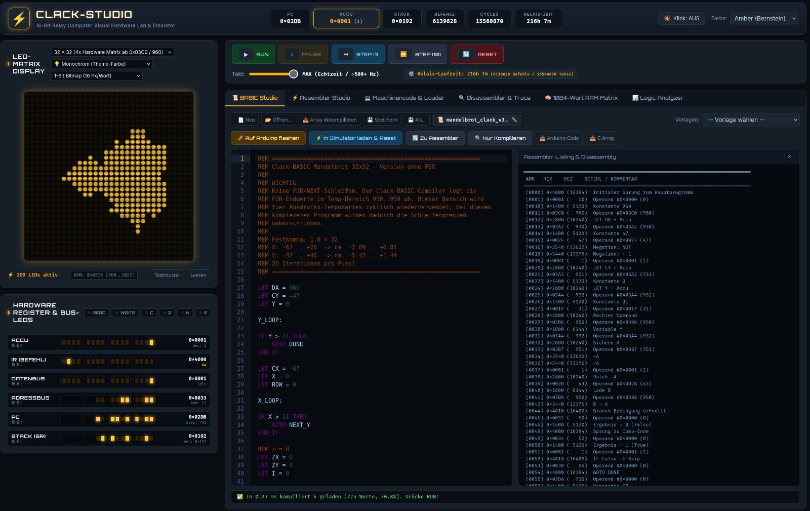
This program executes natively on Peter's physical 16-bit relay computer! It calculates the Mandelbrot set using 16-bit fixed-point arithmetic (scaling factor 256 = 1.0) and drives the electromechanical relays of the 32×32 LED matrix display.
10 REM ========================================================
20 REM MANDELBROT SET 32x32 FOR PETER'S RELAY COMPUTER
30 REM 16-Bit Fixed-Point Arithmetic (Scaling: 256 = 1.0)
40 REM ========================================================
50 CLS
60 MAXITER = 16
70 FOR Y = 0 TO 31
80   CI = (Y - 16) * 16
90   FOR X = 0 TO 31
100    CR = (X - 22) * 16
110    ZR = 0
120    ZI = 0
130    FOR I = 1 TO MAXITER
140      ZR2 = (ZR * ZR) / 256
150      ZI2 = (ZI * ZI) / 256
160      IF (ZR2 + ZI2) > 1024 THEN GOTO 220
170      ZI = (ZR * ZI) / 128 + CI
180      ZR = ZR2 - ZI2 + CR
190    NEXT I
200    PSET(X, Y, 1)
210    GOTO 230
220    PSET(X, Y, 0)
230  NEXT X
240 NEXT Y
250 END
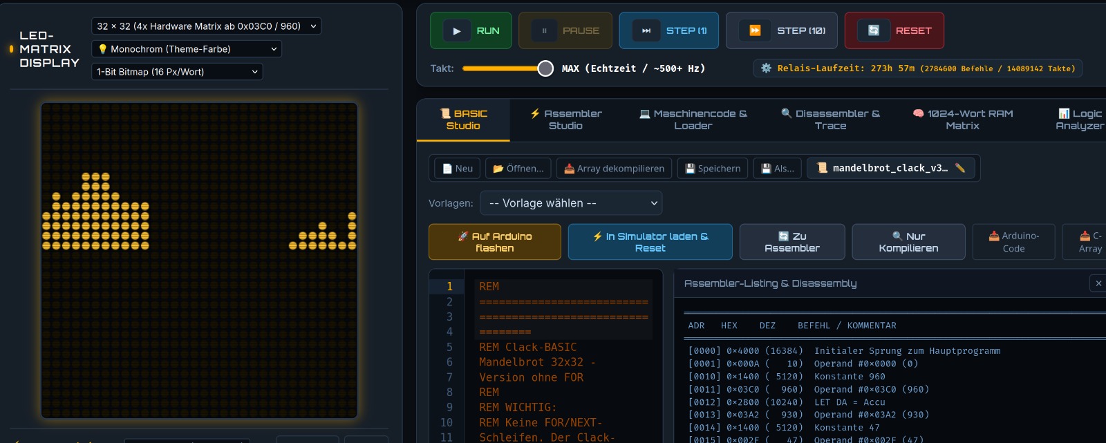
The photograph shows the original LED matrix display of the relay computer after running the Mandelbrot calculation above. The distinctive cardioid and bulb geometry is sharply defined across the 1024 relay pixels!
📊 2. Data Tables & Breakpoints: DATA, READ, RESTORE & STOP
Demonstrates sequential constant streaming from program memory and the programmed hardware breakpoint (STOP) for cycle-level register and memory inspection.
10 REM ========================================================
20 REM CLACK-BASIC: DATA, READ, RESTORE & STOP DEMO
30 REM ========================================================
40 CLS
50 PRINT "STREAMING DATA TABLE:"
60 FOR I = 1 TO 4
70   READ V
80   PRINT "VALUE "; I; " = "; V
90 NEXT I
100 PRINT "PROGRAMMED BREAKPOINT (STOP)..."
110 STOP : REM CPU execution halts here; registers can be inspected!
120 PRINT "RESETTING DATA POINTER (RESTORE)..."
130 RESTORE
140 READ FIRST_VAL
150 PRINT "FIRST VALUE RE-READ: "; FIRST_VAL
160 DATA 100, 250, 42, 888
170 END
💻 Clack CLI Quickstart Guide
Once downloaded, the compiler toolchain can be executed directly in your terminal:
# Grant executable permissions (Linux / macOS)
chmod +x clack-linux-amd64

# Compile BASIC source file into relay machine binary
./clack-linux-amd64 build mandelbrot.bas -o mandelbrot.bin

# Execute program directly in the virtual 16-bit relay emulator
./clack-linux-amd64 run mandelbrot.bas

# Disassemble binary machine code back to assembly mnemonics
./clack-linux-amd64 disasm mandelbrot.bin